Release: 2022-10-25 17:00:40
Introduction
This technical note will describe how a fused optical fiber coupler works and how it is made. Once an understanding of this has been obtained, some of the principals of operation will be made clear at once (bi-directionality, for example).
The Fused Biconical Taper Process
A fused coupler basically consists of two, parallel optical fibers that have been twisted, stretched and fused together so that their cores are very close to each other. This forms a Coupling Region as shown in Figure 1 below. The length of this Coupling Region, L, determines the coupling ratio from one fiber to the other. During the manufacturing process, light is launched into an input port, P, and the output power from each output port is carefully monitored. When the desired coupling ratio is achieved, the fully automated manufacturing process is stopped. The resulting coupler is essentially one fiber with two cores that are very near to one another. This process is known as the Fused Biconical Taper (FBT) process.
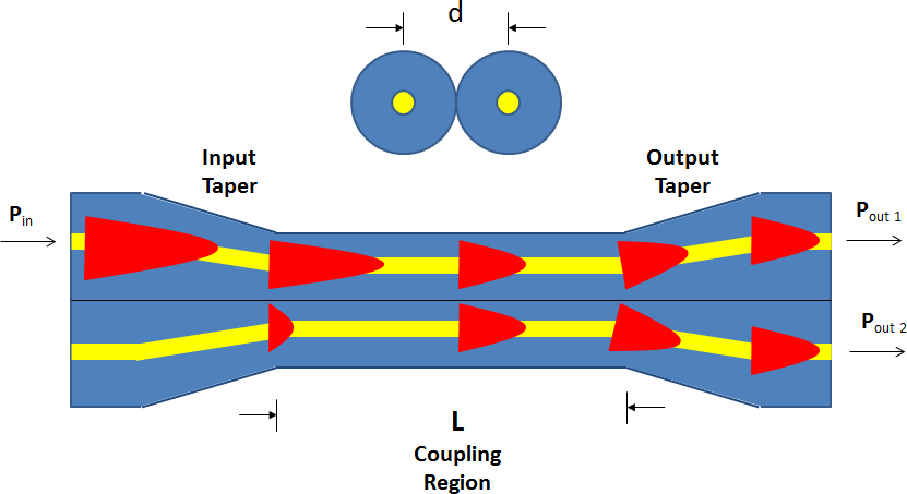
Fig. 1 The Fused Biconical Taper process.
How a Fused Coupler Works
The intensity profile of light traveling down a singlemode fiber is essentially Gaussian; that is, the intensity is greatest in the center and tapers off as the core/cladding interface is approached. The tail ends of the Gaussian profile extend slightly through the core and into the cladding. This tail is called the evanescent wave. Figure 2 represents the cross section of a light wave in an optical fiber. The vertical dashed lines represent the fiber core/cladding boundary. The red tails are the evanescent wave.
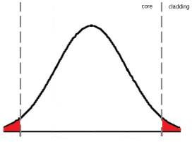
Figure 2. Light propagating down an optical fiber. The red region represents the evanescent wave.
In the FBT process the cores of two identical parallel fibers are so close to one another that the evanescent wave can “leak” from one fiber core into the other core. This allows an exchange of energy, analogous to the energy exchange that takes place with two coupled pendulums. In fact, this is an excellent analogy. The amount of energy exchange is dependent upon the proximity of the two cores, d, and the length over which this exchange takes place, L (see Figure 1). It is easy to see that if the coupling length is long enough, a complete transfer of energy can take place from one core into the other. If the length is longer still, the process will continue, shifting the energy back into the original core. By selecting the proper length, any given power transfer ratio can be realized. This is how a 50/50 or a 10/90 coupler is made.
Let’s consider a few examples using Figure 3. Assume that this device is a 50/50 coupler.
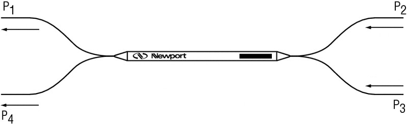
Figure 3. A 1x2 or a 2x2 coupler.
Assume that we launch 1 mW into port 1 and 1 mW into port 4. What do we measure at the output ports 2 and 3? It should be apparent that we will measure 1 mW at each output port, the light from each input port having split into two equal parts. Now assume that we launch 1 mW into port 1 and 2 mW into port 4. What do we get now? Each path gets split into two equal parts again, so now we end up with 1.5 mW at each output port (0.5 mW contribution from port 1 and 1 mW contribution from port 4).
Let’s consider another example, still using Figure 3 and assuming it is a 50/50 coupler. Assume that port 4 is now no longer available. It has been disconnected somehow, perhaps having been cut off. What we have now is a 1x2 coupler. If we launch 2 mW into port 1, it is easy to see that we will end up with 1 mW at ports 2 and 3.
Bidirectionality
In a standard 50/50, 2x2 coupler, the idea of reversing the launch direction is immediately clear. The process is completely bi-directional. Confusion sometimes arises, however, when presented with a 1x2 coupler. The apparent non-symmetry of the device creates the false impression that the device somehow works differently. Continuing the last (1x2) example, what happens if light is launched into one of the two “output” ports; that is, ports 2 or 3? Does 100% of the light exit at port 1? Of course not. Light still “wants” to exit from port 4 as well. So if we consider 1 mW launched into port 2, we will have just 0.5 mW exiting from port 1. Or, if we launch 1 mW into port 2 and 2 mW into port 3, we will have 1.5 mW exiting from port 1. We just need to realize that a 1x2 coupler is just a 2x2 coupler with one fiber cut short, crushed (to reduce back reflection from the end facet), and tucked away inside the housing of the coupler. In this case we can see how an understanding of how a fused fiber optic coupler is made and how it works helps us to understand how this reverse process works.
Wavelength Division Multiplexing
Up to this point we have tacitly assumed that a single transfer of energy has occurred from one fiber to the other. In reality, energy transfers back and forth between the two fibers many times over the coupling region (also called the Interaction Length). The transfer rate is a function of wavelength, so if a wavelength is used that is different from the design wavelength, the energy transfer (or coupling ratio) will be different. As an example, assume that two different wavelengths are launched into the two input ports of a coupler. The energy transfer graphs would look very much like what is shown in Figure 4 below. In fact, the interaction length (or coupling region) could be adjusted during the manufacturing process such that all of the light from both wavelengths exits at the same exit port (this is marked with a vertical green line in the figure). This is how Newport’s F-WDM Wavelength Division Multiplexers are made. Note that these couplers are also bi-directional, capable of splitting the two wavelengths when used in the reverse direction (Figure 5).

Figure 4. Energy transfer of two wavelengths in a fused coupler.
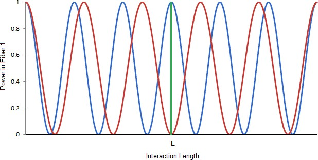
Figure 5. Energy transfer is bi-directional in a fused coupler. Here, two wavelengths are launched into fiber 1 and each exit separately at the other end (the green line indicates the far end of the coupler). This is an example of a wavelength division multiplexer.